Unity Pixelated Art Style In URP
I’m considering diving into game dev for a rather long period from now on, and was managing to find a possible way to build a traditional RPG that can be handled only by myself from any aspect such as assets like models, animation, sound design, and system. I think I should write down my progress and tech details in the future, so that I can feel the speed of my progress and share my experience to help those who are struggling like I was.
![]()
Unity Pixelated Art Style In URP
Currently I’m trying to find a suitable and simple art style for this project to work with, and I saw some pixelated 3D art style created by t3ssel8r by coincidence. Though he didn’t offer any tutorial for beginners to work with, however I am not beginner at all, (Nope) I can still get some information from the comments below his video or twitter especially on how he managed all those amazing works.
![]()
In order to get a harmonious pixelated art style like t3ssel8r’s, I tried to do some breakdown to his final result like the one above.
- Cel shading (also called toon shading, which is more familiar to most developers), a necessity since it can reduce the color range, which is quite important for pixel art in its definition.
- Down sampling, but I find his outcome differ from those pixelated style made by down sampling from camera output, because his method keeps pixel moving smoothly in screen rather than making the whole screen low resolution, so I think he may used some custom render pileline, which is still an unknown area for me to conquer. This part will not be included in this post, maybe a relevant post later.
- Outliner, also a significant element in most pixel art. In traditional pixel art, the outline should be seamless, and outline should appear in any sharp edges as if it’s some kind of highlights. So seamless outlines drawn by combining depth, normal, and scene color information is desired.
Cel Shading
I started to work with cel shading first, and found a developer Robin Seibold uploaded a cel shader graph with great expansibility in this video (BTW his video editing is absolutely fabulous). So I copied one from his video (great thanks to Robin) and modified the shader to suit my own needs (just added more borders to the shadow rather than only one border between lit area and unlit area).
I’ve also tried to implement gooch shading, but eventually failed to make it support multiple light sources. So I’d implement this later and put these content in another post if I succeed.
To follow the tutorial by Robin, I found my URP version so old that doesn’t include some file that the tutorial may use. Mine is only about URP v10.x.x because that’s already the highest version Unity 2020 can support according to this official GitHub repo. So I upgraded my Unity to the newest LST 2021.3, which supports URP 12.x.x and dynamic additional light shadows, and made my environment as close to the tutorial as possible.
Outcome
For a basic cel material like this one I made below:
![]()
It is coded by following Robin Seibold‘s tutorial I mentioned before, and added an effect that create a certain number of shadow edges, which can be done by just tweaking the diffuse stuff.
I found a free model of Honkai Impact 3rd on Sketchfab to test out the cel shading:
![]()
And I think the effect reaches my desire. This model contains too much details which I can never create in limited time. Currently I just care that whether the shadows, rim, specular looks nice after pixelate, which seems not bad at least.
Seamless Outline
I used to think outline easy and handy, but this time, it takes me 3 or 4 days to get everything nearly right.
![]()
Outline is not edge case like “Pixel Perfect Cam”, so I found quite a lot sources as references:
- Robin Seibold again, he built a clean outline and taught how to write a renderer feature in URP. Although not using his edge detection method nor using renderer feature to generate normal texture, I learnt a lot about renderer feature by following his video.
- James King, he tried to recreate t3ssel8r‘s outline and pixelated art style in his Three JS project and put it on GitHub.
This article explained how to draw outline with depth texture and normal texture like the following image does (image from that article)
![]()
To get start with edge detection algorithm, we need the references to a few textures first.
Textures
Depth Texture
Depth texture is much easier to get than normal texture. In order to make URP render a depth texture, check “Depth Texture” in URP Assets. After so, the _CameraDepthTexture should be rendered and can be seen through Frame Debugger. In shader graph, Scene Depth node is also provided to access depth conveniently.
![]()
To know more about depth in game, make sure to check this article.
It’s noticeable that in orthographic cam, raw depth is already linear01, so you shouldn’t use linear01 mode nor eye mode in shader graph when using depth node.
Normal Texture
There’re several ways to get a normal texture:
G-Bufferin deferred rendering_CameraNormalsTexturerequested byConfigureInput(ScriptableRenderPassInput.Normal)- Draw your own normal texture with
ScriptableRendererFeatureby overriding material on every objects (another version of replacement shader)
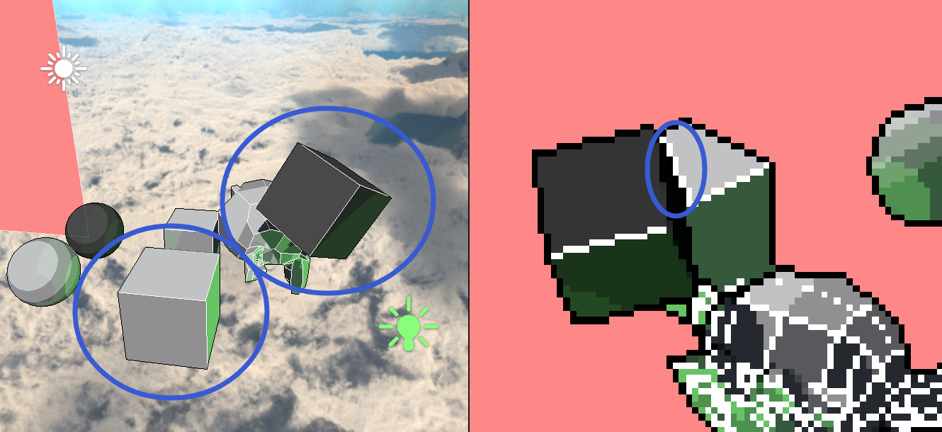
It’s worth notice that G-Buffer and _CameraNormalsTexture stores world normal since those data are usually used to calculate shading / lighting stuff. Drawing your own texture with ScriptableRendererFeature may give you more customizable result, and of course you can draw view normal directly by using this method. However, since override material / replacement shader will override your original shaders, vertex displacement resulted by vertex shader will not be applied, nor normal map or any stuff to do with your original material. As screenshot shows below, _CameraNormalsTexture and G-Buffer hold details and vertex modifications which ScriptableRendererFeature doesn’t.
![]()
R: view normal by override material
G-Buffer
The easiest one is selecting Rendering Path as Deferred in URP renderer data, and set camera depth texture mode to DepthNormal in script.
![]()
Because deferred rendering generate G-Buffer, which is used to save scene info in GPU to assist shading computations. The normal texture of the scene can be read from it. With URP 12, it is stored in _GBuffer2.
![]()
The normal texture in G-Buffer is world normal, and it stores negative values, which means even though some pixels are pitch black visually, it still stores normal information which can be transformed to view normal by matrix.
![]()
R: view normal converted
Scriptable Render Pass Input
World normal texture can be get not only in deferred rendering, but also in forward rendering if you requested in a renderer feature. Only one line of code can do it: ConfigureInput(ScriptableRenderPassInput.Normal);
After adding this renderer feature to the URP renderer data, _CameraNormalsTexture will be rendered just the same as the normal texture in G-Buffer.
Override Material
In Built-in pipeline, you can use Replacement Shader to render the whole scene in a single material. But you can’t use it to control the camera in URP since this function is not contained in Camera class, instead you can use override material to achieve same result.
To do so, a basic understanding to renderer feature work flow is required. Here is a Chinese reference about it.
In a word, you may wanna use a view normal material as override material and render your scene into a render texture you created. I’m not that familiar with these currently, so just some ambiguous guidance below.
To create a render target:
1
2
private readonly RenderTargetHandle normals;
normals.Init("_SceneViewSpaceNormals");A customized
RenderTextureDescriptorcan offer options like color format, texture size, etc. It contains all the information required to create a render texture.1
2
3
4// Copy from cam settings
RenderTextureDescriptor normalsTextureDescriptor = cameraTextureDescriptor;
// Customization
normalsTextureDescriptor.colorFormat = RenderTextureFormat.ARGB32;Create a temporary render texture with given parameters, and set it up as a global shader property with nameID. Then redirect render target to the temporary RT, and clear the attachment into the color or depth/stencil values (depending on the format of this attachment)
1
2
3cmd.GetTemporaryRT(normals.id, normalsTextureDescriptor, FilterMode.Bilinear);
ConfigureTarget(normals.Identifier());
ConfigureClear(ClearFlag.All, Color.black);Create drawing settings and set override material
1
2
3
4DrawingSettings drawSettings = CreateDrawingSettings(shaderTagIdList, ref renderingData, renderingData.cameraData.defaultOpaqueSortFlags);
drawSettings.overrideMaterial = normalsMaterial;
FilteringSettings filteringSettings = new FilteringSettings(RenderQueueRange.opaque, layerMask);
context.DrawRenderers(renderingData.cullResults, ref drawSettings, ref filteringSettings);Release temporary RT after usage
1
2
3
4public override void OnCameraCleanup(CommandBuffer cmd)
{
cmd.ReleaseTemporaryRT(normals.id);
}
Opaque Texture
_CameraOpaqueTexture provides a snapshot of the scene right before URP renders any transparent meshes. In shader graph, SceneColor node would sample this texture as return value.
By enabling the opaque texture, we can draw outline with reference to the original pixel color. This texture can be also used to create effects like frosted glass, water refraction, or heat waves.
To enable this texture, check the checkbox under depth texture checkbox in URP asset.
Edge Detection
After preparations of view normal texture, depth texture, opaque texture, it’s time to do real edge detections with these references.
Edge detection in game is using basically the same tech in image edge detection. You sample a pixel and its neighbors, comparing their difference. However, since we got both normal and depth textures, it’s possible to achieve more complicated effect by combining them together. James King is doing a really nice job on this, and made the outline only one pixel wide, which is a significant factor contributing to the overall appearance of the scene. So I’d explain his logic and talk about issues I encountered when implementing his method in Unity.
Depth Edge
Preprocess
As I said before, raw depth in orthographic cam is already linear01, but the issue is that when far plane and near plane are far away from each other, the difference between two depth value in the texture becomes too tiny to work with. After my experimenting, it would be clear and reasonable when
far plane - near plane = 20, so I made a multiplier by referencing far plane and near plane to change my depth scale making it reasonable.Depth values would be difference depending on the platform:
- Direct3D-like, Reversed Z Buffer : 1 at the near plane, 0 at the far plane
- OpenGL-like, Z Buffer : 0 at the near plane, 1 at the far plane
This reverse flag is stored in
_ProjectionParams.x, it can also be accessed inCameranode in shader graph.Process
Now sample a few points around the original pixel, and get the bias by
bias = neighbor - center. If using this bias directly, both edges inside the object and outside the object will be drawn, which results in at least 2 pixel wide depth outline. But this can be fixed by clamping bias to [0, 1] or [-1, 0], leaving only one pixel wide outline that either nearer or farther one. After so, usesmoothstepto control the visibility of edges with different biases.
Then we are done with it.
1 | // Pseudo Code |
Normal Edge
Preprocess
If you generate view normal texture by overriding materials, you should remap your view normal material from [-1, 1] to [0, 1] since when rendering to the render texture, negative values will be set to 0. By doing so you won’t lose any normal information. You can remap it back to [-1, 1] when sampling your view normal texture.
Edge Sharpness
The sharpness is the easiest one to understand in the following parts.
sharpness = 1 - dot (normal, neighborNormal)Normal Indicator
Similar to depth edges, we’d like to get normal biases between it’s neighbors:
bias = normal - neighborNormal. Since the bias is afloat3, it can’t be simply clamped to cut one side of outline (the normal outline is also 2 pixels wide as shown below)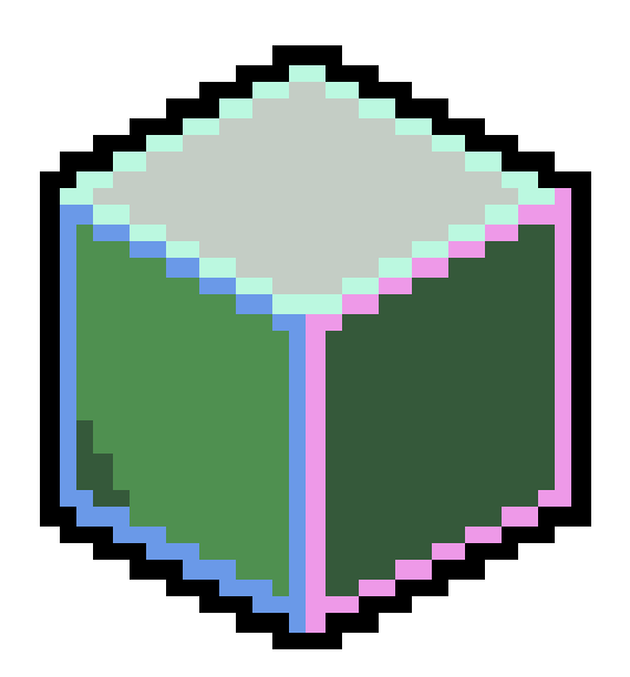
To make the normal outline also one pixel wide, James declared a direction vector3 (e.g. float3(1, 1, 1)) as parameter and get the dot product of which and normal bias:
dot(bias, direction vector). Since the normal texture is in view space, such dot product can cull edges on faces in opposite direction of the direction parameter.
View Space Normal This dot product can then be passed in
smoothstepto get control of edge strength and cull the undesired edges. For example, if the direction parameter isfloat3(1, 1, 1), then only edges on faces towards up-right and pointing out of screen will be drawn.Depth Indicator
Applying one pixel outline though, it’s unsurprised to find that normal edges shows up outside the object, and it also draws outlines on concave edges.
Even two cubes have no contact
The normal texture indeed has difference there
And happen to match the requirement of the direction parameter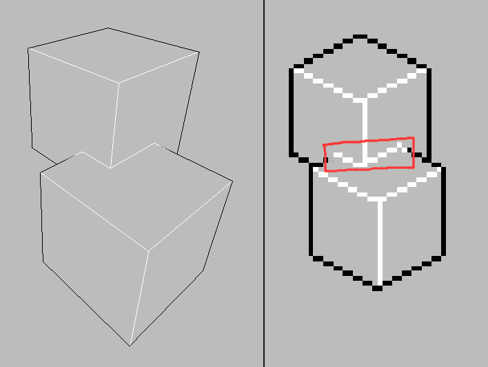
The concave edges in red box are not desired in most pixel art To eliminate these outlines, we can make only the shallower pixel detects the normal edge. So depth bias is required here to calculate the depth indicator. Get the average depth bias of the original pixel, if the value is negative, it means the pixel is farther than its neighbors, which should be culled when detecting normal edges; otherwise it counts.
So the final normal edge strength can be represented as follows:
1 | // Pseudo Code |
Outcome
Two parameters to control depth and normal edge strength may be wanted. Usually, our brain would like the outline of an object darker, and the normal edges brighter:
1 | float strength = |
![]()
To add scene color to the outline, I analysed the pros and cons of _color = _texel * strength and _color = pow(_texel, strength), and found the method below is my favorite.
1 | _color = |
![]()